

گارانتی سلامت فیزیکی کالا
موجود در انبار فروشگاه میکرو پردازش10
تومان75,000
10 عدد در انبار
-
نقد و بررسی اجمالی
output.
debugging:Input a 50% duty ratio signal to PWM/GND and adjust the relative
amplitude short cap. The frequency is 1KHZ-3KHZ, Measured VOUT and GND with a
multimeter and it will display 5V. Adjust potentiometer to make sure display
5.00V on multimeter. This will calibrate your pulse signal to this module.
calibrated.
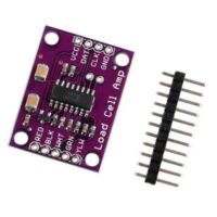
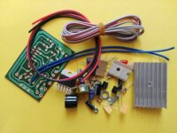
PWM transfer voltage module LC-LM358-PWM2V converts the PWM digital signals
into 0 to 10V analog signals.
control boards. The output voltage is regulated by adjusting the duty ratio of
the PWM. The modules are small in size and easy to use in different places.
Using
single chip embedded technology;
Peak
4.5v to 10V level, jumper inserted at 5V. This level of signal mainly for
conventional industrial control card (such as MACH3 board Card) 5V CPU
interface;
Easy
to operate, can be fine-tuned by potentiometer;
Select
the PWM signal input level range through short cap;
Module
is small, easy to carry and use;
Module
operating voltage: DC12V-30V (power requirements: greater than 100mA);
PWM
signal reception frequency range: 1KHz-3KHz;
Peak
12 to 24V level, jumper inserted in the 24V. This level of signal is mainly
aimed at the conventional PLC interface;
Conversion
range: 0% -100% PWM to 0-10v voltage;
Allowable
error: 5%;
MCU
embedded technology
to operate, fine tuned by potentiometer
Parameters
Work Voltage:DC 12V-30V; (> 100MA)
used for normal controller or 5V MCU
‘24V’. This level is used for normal PLC controller
Interface:
VCC:
working power 12-30V
GND:
ground
PWM:
input PWM signal positive
GND:
input voltage ground
VOUT:
Output voltage: 0-10V
GND:
output ground
-
توضیحات کوتاه
ماژول مبدل PWM به ولتاژ 10-0 ولت